Pneumatic conveying system design is often treated like a simple pipe and blower problem. That is why so many systems choke mid-shift, wear bends prematurely, or shred delicate pellets. You expect clean transfer and steady rates. Instead, you get dust clouds, plugs, or unexplained motor alarms.
Why do fragile pellets arrive dusty at the discharge even when the spec sheet looks solid? The answer usually lies in how the material behaves under air velocity, not in catalog dimensions. Every particle has a personality. Bulk density, moisture, abrasiveness, and friability dictate how it moves, collides, and accelerates. When these traits are ignored, downtime becomes routine.
This guide will convert engineering principles into practical design decisions. It will avoid generic pros and cons and focus on what actually keeps a system stable. H&H Design & Manufacturing understands how material behavior, line geometry, and real plant layouts shape reliable dry bulk systems.
Quick Strategy Snapshot for Busy Engineers
Start with material physics, not hardware. Bulk density, moisture behavior, particle shape, and attrition index decide the conveying regime before a single pipe or blower is selected.
Velocity gates determine stability, not horsepower. Systems stay reliable when they run comfortably above entrainment or confidently below it. Designing near carrying peaks guarantees turbulence and plugs.
Feed discipline is more important than pipe diameter. Stable pickup and consistent mass flow prevent surge events that wreck elbows, blind filters, and collapse slug formation.
Wear should be intentional, not accidental. Direct abrasion into replaceable elbows, liners, and protected transitions instead of letting the line cannibalize structural pipe.
Instrumentation keeps systems honest. Pressure, flow, and temperature tracking prevent silent drift. Plants that measure reality outperform plants that hope it stays steady.
Material Behavior and Flow Regime Selection in Pneumatic Conveying System Design
Material properties dictate the entire system. They determine the flow regime, the velocities that keep particles suspended, how fast wear happens, and the air mover you must choose. Systems fail when you force material into a preset regime rather than letting its behavior guide the design. When the material is respected first, conveying becomes predictable instead of chaotic.
Material Profiling That Actually Matters
Before choosing pipe size or blower specifications, profile the material. Each item in the list below directly influences conveying stability.
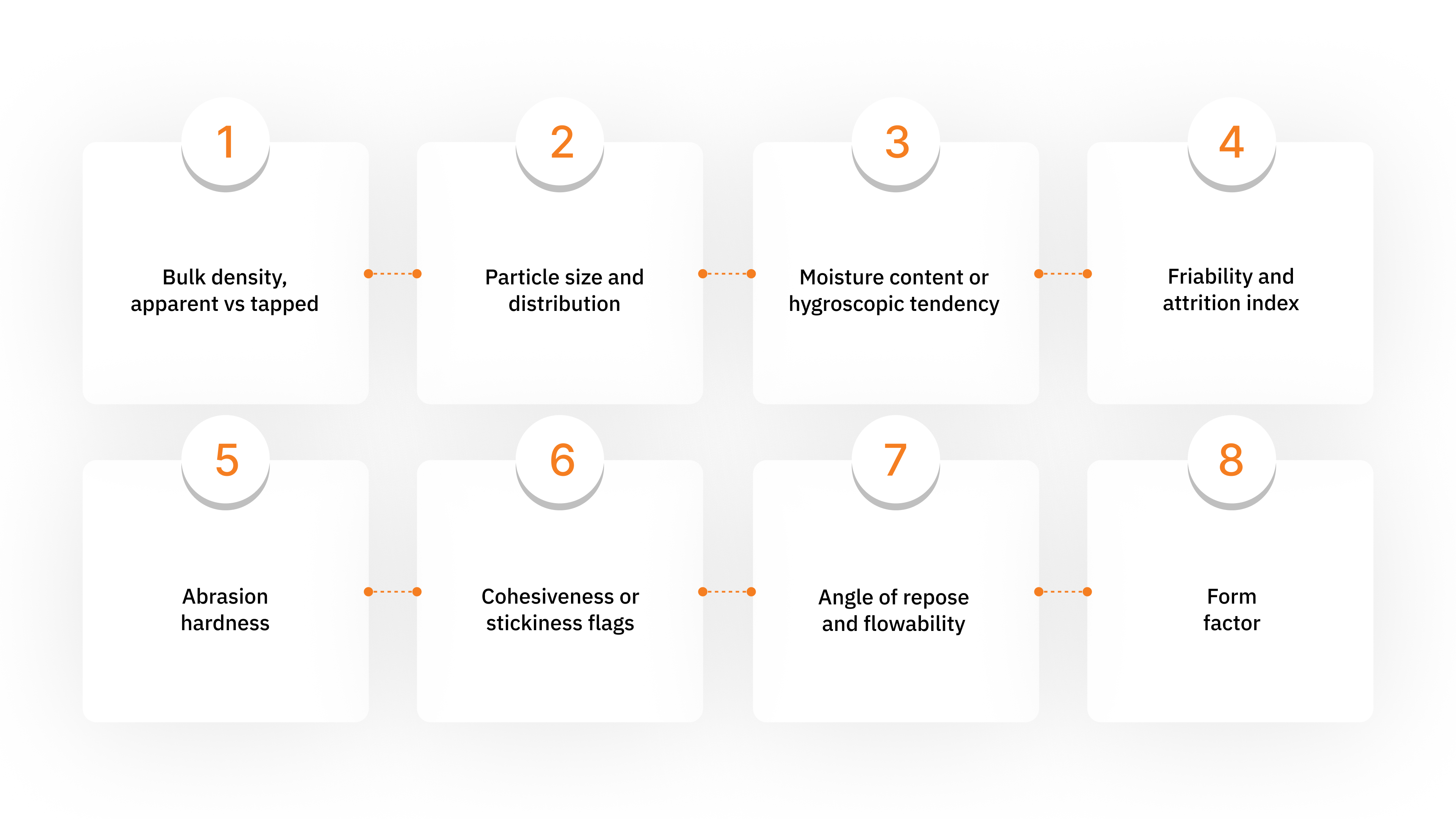
Bulk density, apparent vs tapped: Apparent density is what sits free in the hopper. Tapped density reveals compaction under vibration. The difference indicates how easily the material settles and plugs.
Particle size and distribution: Fine powders entrain faster but pack easily. Mixed distributions cause uneven loading and sudden saltation failures.
Moisture content or hygroscopic tendency: Moisture increases surface friction. Hygroscopic materials absorb humidity in-air lines and form cakes.
Friability and attrition index: Fragile pellets fracture on impact. Dense phase or lower velocity paths reduce breakage.
Abrasion hardness: Hard particles cut bends and tees. Running them at high velocity guarantees short elbow life.
Cohesiveness or stickiness flags: Sticky powders cling to walls. They demand controlled pickup sections or assisted feeding.
Angle of repose and flowability: A flatter angle signals free flow. A high angle indicates sluggish discharge and the need for mechanical aids.
Form factor: Fibrous, flaky, pellet, and granule shapes each settle differently and respond to velocity changes in unique ways.
Fragile or abrasive materials perform better in dense phase due to lower velocity and fewer impacts. Sticky, wet, or fibrous products are unstable in both regimes and need specialized pickup or pre-conditioning.
When Dilute Wins, When Dense Wins
The following lists help you decide the correct regime based on material traits and operational expectations.
Ideal dilute candidates: Free-flowing pellets, non-abrasive granules, low dust fines, consistent particle shapes.
Poor dilute candidates: Friable pellets that break under collision, highly abrasive powders that damage elbows.
Ideal dense candidates: High abrasion media such as mineral powders, fragile shapes that benefit from controlled low velocity slugs.
Poor dense candidates: Sticky powders, fibrous materials, foods or polymers that smear or bind under compression.
Strand or medium phase cases: Controlled surfaces with stable pickup velocity where full entrainment is unnecessary and impact reduction is a priority.
You can read the material perfectly and still get blindsided by airflow. Once the regime is chosen, velocity limits and line geometry decide whether your design behaves like a conveyor or like a clogged straw.
Velocity Boundaries, Pressure Drop, and Layout Discipline in Pneumatic Conveying System Design
Selecting a dilute or dense phase is not enough. The system’s stability depends on velocity limits, pressure losses, and how the line geometry handles moving solids. These elements decide whether your system runs daily or clogs unexpectedly. Poor air path discipline overwhelms even high-capacity blowers.
Saltation Velocity and Carrying Capacity
Saltation velocity is the minimum air speed that keeps particles suspended. Anything slower allows particles to settle and build a moving bed. The dilute phase must stay safely above this threshold. Dense phase works below it, creating controlled plugs that reduce damage to fragile material.
Saltation rules
Dilute: operate comfortably above entrainment
Dense: operate below with predictable plug flow
Avoid the peak region: unstable and hard to control
Pressure Drop and Velocity Profile
Pressure drop rises sharply once solids enter. Particle acceleration, wall friction, and collisions consume energy. Downstream pressure falls, gas expands, and velocity increases. This pushes the highest impact energy into elbows and receivers.
Core contributors to ΔP
Moving particles from rest to conveying speed
Continuous wall abrasion
Particle-to-particle collisions that break material
Routing and Elbow Fundamentals
Line routing dictates reliability. Each bend increases pressure loss and wear. Minimize bends and use long radius elbows sized four to six pipe diameters. Avoid back-to-back elbows and short runs after pickup, which encourage settlement. Pipe diameter should balance velocity and pressure, not mimic standard utility piping.
The Series 156 delivers reinforced dual-belt compression for dense materials, built by H&H Design to handle cement, feed, and fertilizer in demanding industrial environments.
You can tame velocity and pressure on paper, but the line will still fall apart if the material enters badly. Once the air supply and feed rhythm go unstable, every bend and blower becomes a problem.
Air Delivery, Feeding Stability, and Control Systems in Pneumatic Conveying System Design
Pneumatic conveying is an airflow problem first. You move material by controlling pressure, velocity, and air volume. Most shutdowns come from unstable air conditions and poor pickup behavior, not from weak motors or thicker pipes.
Air Movers and Peak Design
Air movers decide how much pressure and flow you can sustain. Each option has a distinct operating window, so matching it to your system’s pressure drop curve matters more than brand or horsepower.
Common air mover behavior
Centrifugal fans: Moderate pressure, variable flow. Effective for short, dilute runs and low-abrasion material.
Rotary PD blowers: Constant volumetric delivery. Strong choice for long layouts where stable velocity is critical.
Compressors: High pressure. Used for dense phase, long distances, and materials that cannot tolerate high velocity.
Key sizing rules
Select using vendor performance curves based on the actual system ΔP.
Size for peak feed conditions, not nominal rates.
Keep the operation away from relief valves and motor limits to prevent stalls.
Include inlet filtration and silencers to avoid backpressure and noise spikes.
Review the air temperature rise to protect elastomers and seals.
Feeding, Venting, and Diversion
You cannot stabilize conveying if the material enters unevenly. The feed point is where most line failures begin.
Pickup and feed fundamentals
Metering devices must be sized for peak feed rate, not sales literature.
Rotary valves need enough pockets per revolution to avoid starvation.
Screw feeders should maintain uniform mass flow, not pulsed dosing.
Air discipline at feeders
Pressure dilute systems need venting above the feeder to prevent an airlock.
Multi-pickup and multi-drop lines require airtight diverters so airflow sees one path at a time.
Avoid gravity tees and open manifolds that bleed velocity and create dead zones.
Instrumentation and Filtration
You cannot run blind in pneumatic transport. Every system drifts over time.
Minimum telemetry
Line pressure at pickup and mid-line
Airflow before solids entry
Temperature to track density changes
Filtration rules
A conveying line needs a dedicated baghouse sized for the transport dust load.
Silo vents are not process filters and will clog quickly.
Plan purge air, isolation valves, and emissions limits during design, not after commissioning.
Air and feed stability will keep the line moving, but nothing travels forever without scars. Once solids start colliding with steel, the real maintenance story begins.
Wear, Reliability, and Maintenance Planning in Pneumatic Conveying System Design
You do not eliminate wear. You choose where it happens. A pneumatic conveying line should sacrifice material at predictable locations instead of letting abrasion destroy pipe runs at random. When you direct impact energy and schedule maintenance, uptime becomes routine rather than a guess.
Impact Zones and Durability
Impact always concentrates at elbows, tees, and transitions. These zones need materials that tolerate abrasion and impact without collapsing.
Design choices that protect critical areas
Wear resistant elbows and ceramic liners: Place them at bends, velocity drops, and high loading points. These surfaces absorb damage and preserve the main line.
Velocity reduction in sensitive sections: Lower conveying speed before fragile material enters sharp bends. Fewer collisions mean fewer fines and longer elbow life.
Dense phase and support structure: Dense phase reduces particle speed but transfers vibration into the line. Use strong pipe supports, anchors, and shock mounts so joints do not fatigue.
A reliable line accepts that damage will happen. It chooses surfaces that are easy to replace or reline, not structural pipe.
Noise and Inspection
Blowers and moving solids generate industrial noise. Operators, control rooms, and maintenance crews face constant exposure if you do nothing.
Good practices that improve reliability
Sound enclosures or acoustic panels around blowers. These reduce noise at the source and protect personnel.
Inspection ports and service paths built before commissioning. Maintenance becomes routine when you can see and reach problem zones.
Proactive schedules instead of waiting for failures. Track erosion in elbows and valve housings and replace parts at planned intervals.
A conveying system that treats wear as an expected phenomenon runs longer, costs less to maintain, and stays predictable for the operators.
The Series 330E delivers high-volume filling with automated carriage control and seamless conveyor integration, built by H&H Design & Manufacturing. Engineered for continuous-duty industrial environments, it provides consistent accuracy, reduced handling, and reliable throughput for demanding bulk operations.
Wear teaches you patience, but mistakes teach you expense. Once you know where abrasion belongs, it becomes obvious where poor design quietly sabotages everything else.
Common Pneumatic Conveying System Design Mistakes and How To Avoid Them
Most conveying failures start in design, not during operation. They come from bad assumptions, improper sizing, and ignoring how the material behaves. Avoiding these mistakes gives you predictable rates, stable velocities, and fewer stoppages.
Below are the most damaging errors and the direct actions that prevent them:
Designing at carrying capacity peak: Always design above or below the peak, never right on it. Peak regions amplify small fluctuations.
Miscalculating pressure drop: Include line losses, fittings, filters, and acceleration zones. Idle airflow values do not represent real conditions.
Choosing flow regime by price, not material: Dilute is cheaper to install but often expensive to run for fragile or abrasive materials.
No feeder venting: Pressure systems require venting above feeders or you will get airlock.
Too many elbows or back to back bends: Each bend increases wear and ΔP. Space them and use long-radius elbows.
Undersized air movers: Match blower capacity to actual, measured ΔP. Oversizing pipe does not compensate.
Inconsistent dosing in dense phase: Erratic feeding collapses slug flow and causes plugs.
Weak supports: Vibration and fatigue destroy joints. Reinforce the line at stress points.
Ignored dust collection: Conveying air needs a baghouse. Silo vents will blind quickly.
Over reliance on silo vents: They are not process filters and cannot protect the system.
Missing control instrumentation: Line pressure and airflow must be monitored continuously.
No emissions plan: Capture, purge, and discharge need to be designed, not improvised later.
Mistakes can ruin a system quickly, but fixing them is never luck. Once you understand the traps, you look for partners who design to avoid them from day one.
Why H&H Design and Manufacturing Matters for Pneumatic Conveying System Design
AT H&H Design & Manufacturing, we do not treat pneumatic conveying as a commodity or a bolt-on accessory. Every system we design starts with the material and the conditions you run in. Your product, layout, feed rhythm, and wear zones define the engineering decisions. Our job is to create a line that works every day, not a design that only looks correct in a brochure.
We control every step of the process. Our team designs, fabricates, installs, and commissions equipment in-house. Because we build and support our own machines, we take responsibility for how they perform. When you bring us abrasive powders, fragile pellets, or sticky feeds, we do not try to fit them into a standard template. We design around their behavior and the geometry of your plant.
What you can expect from us
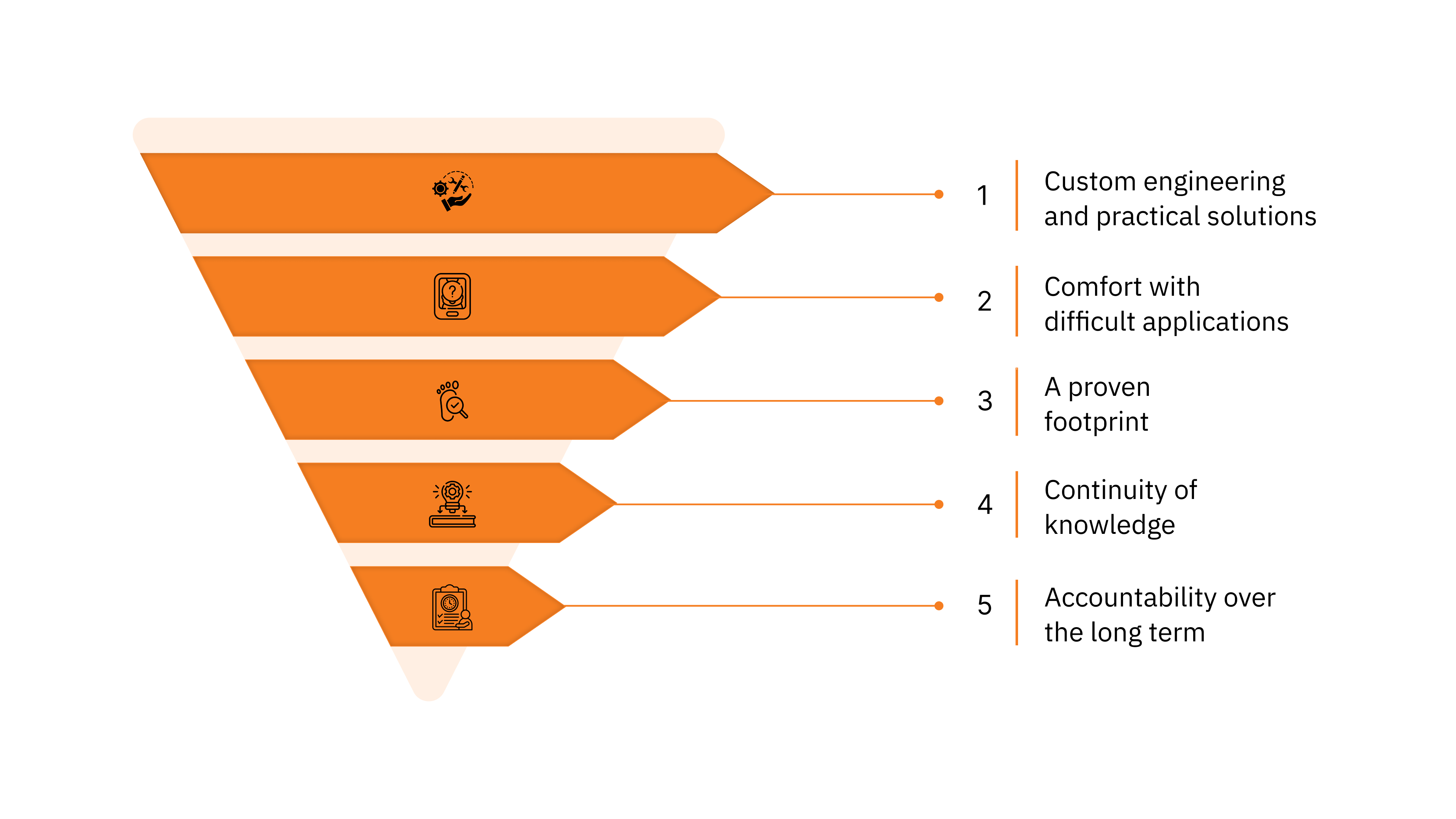
Custom engineering and practical solutions: We modify existing lines, upgrade feeding and airflow, or design completely new systems when the material demands it.
Comfort with difficult applications: Multi-pickup routes, dense phase for abrasive media, or fine powders that cake and bridge are treated as engineering problems to solve.
A proven footprint: Our equipment runs across the United States, Canada, Mexico, South America, and the Middle East.
Continuity of knowledge: When we acquired Tech Packaging Group, we preserved legacy system expertise instead of abandoning older clients.
Accountability over the long term: We communicate directly, meet deadlines, and provide references from active installations. That is why many customers return when they need work done right.
Ready to reduce dust, contamination, and downtime? Talk to H&H Design & Manufacturing about the Series 110DS-P. Call (620) 421-9800 or email sales@hhdesignmfg.com to discuss your application.
Conclusion
Good pneumatic conveying system design starts with the material. When you understand particle behavior, velocity limits, and how air interacts with your feed, the routing and hardware choices become straightforward. Designing around physics prevents chronic plugs, elbow wear, and unstable throughput.
Ask yourself one question first: does your line behave differently when the hopper moisture changes or when feed rate rises only a little? Then another: are your elbows, diverters, or filters doing their job, or are they compensating for unstable pickup and air control?
If your material spikes, plugs, or sheds dust, a custom system may be the right answer.
If you want to discuss a project, reach out to us at H&H Design and Manufacturing. Our team will walk you through options grounded in real engineering, not guesswork.
FAQs
Q: How do I size a pneumatic conveying system when the production rate changes hour to hour?
A: Size to the highest credible demand, not the average batch. Systems designed around peak throughput maintain stability when the line surges. Designing to midpoint values leads to intermittent underflow, starved pickup, and unpredictable transfer.
Q: What should I do if my conveying line works well during startup but fails after temperature changes?
A: Air density shifts with temperature, altering velocity and friction. Set monitoring thresholds that account for seasonal variations, not single test runs. Thermal drift can collapse stable operating windows if left unmanaged.
Q: How do I protect downstream processes from minor conveying dust that bypasses filters?
A: Add secondary localized capture at discharge points to intercept fine escape. Use enclosed transition hoods that channel airflow into controlled extraction instead of open receiving zones. Small dust escapes often occur at impact surfaces, not the main filter.
Q: Can pneumatic conveying be used in environments where frequent material changeovers are required?
A: Yes, but design around isolation, purge capability, and easy-clean sections. Modular inlet assemblies reduce downtime between materials. Quick access to transition points prevents cross contamination during changeovers.
Q: What is the best approach when conveying systems produce subtle off-spec batches even without visible plugs?
A: Validate feed uniformity and feed rhythm before adjusting equipment. Slight dosing irregularities distort mass flow consistency across the cycle. Quality drift often appears long before a full blockage occurs.
Q: How should I manage conveying in a facility where operators vary widely in experience?
A: Favor systems with defined visual indicators and limited manual adjustments. Procedures that rely on subjective judgment invite inconsistent performance. Clear instrumentation and labeled checkpoints keep operation stable across shifts.