Introduction
Incline belt conveyor design is a performance-critical problem where angle, load, belt type, and drive capacity must be resolved together — before the first component is selected. These parameters interact. Misread one, and you're looking at material rollback, belt slippage, premature drive failure, or product damage.
According to CEMA standards, most incline conveyor failures trace back to operating too close to theoretical angle limits — without accounting for real-world variables like vibration, humidity, and load variation. The gap between "tested ceiling" and "safe operating range" matters more than most specs suggest.
Consider a conveyor designed to run at 25° when 25° is the tested maximum. There's zero margin left for belt wear, a humid morning, or an uneven feed rate. That's not a design — it's a deadline waiting to happen.
What follows covers each essential design parameter, where the real limits sit, and what happens when the interactions between them are underestimated.
Key Takeaways
- Incline angle drives every downstream decision: standard flat-belt conveyors top out at 18–25°, and going steeper without design adjustments causes slippage
- Quantify product weight, dimensions, center of gravity, and bulk density before committing to any angle or belt
- Belt selection is driven by incline angle and product type, not preference
- Drive sizing must account for full load at steepest incline, not average conditions
- Tight spatial constraints routinely force trade-offs between angle, belt type, and throughput
What Design Considerations Define an Incline Belt Conveyor
An incline belt conveyor moves materials between two elevations along an angled plane. The angle of incline creates gravitational forces that directly oppose belt traction, drive capacity, and product stability.
Unlike horizontal conveyors — where variables like belt tension and speed operate within forgiving ranges — incline conveyor parameters are tightly interdependent. Increasing the angle, for instance, forces recalculation of belt type, motor power, and conveyor length all at once.
The design process follows a strict sequence:
- Spatial constraints define the geometric envelope and angle range
- Angle range governs belt selection and drive requirements
- Belt and drive specs determine whether the product moves safely at the required throughput
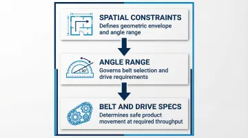
This dependency chain means belt type can't be selected before the angle is confirmed, and the angle can't be finalized without first understanding the product characteristics and available floor space.
Incline Angle: The Governing Design Parameter
Nominal Operating Range and Limits
Incline angle is the primary design variable that determines everything downstream. It is not a preference but a calculated output derived from rise height, available floor run, and product characteristics.
Standard flat-belt incline conveyors operate effectively up to approximately 18–25°, with the upper boundary varying by product type. CEMA's *Belt Conveyors for Bulk Materials* shows maximum angles of 10–20° for most bulk solids, while industry guides cite 18–25° for favorable materials with adequate friction. Cleated belts extend this range to approximately 40–45°, and corrugated sidewall belts can accommodate angles from 20° up to 90° (vertical).
Calculating Maximum Safe Incline Angle
The formula for calculating maximum safe incline angle uses product tilt-test data: δmax ≤ arcsin(HT/LT), where HT is the height at which the product begins to slide and LT is the total length of the test surface. This theoretical maximum must be reduced to an effective operating angle (δeff) to account for belt speed, vibration, humidity, and surface wear.
Safety margins are mandatory. CEMA design guidance recommends applying a 10–15% reduction from the theoretical maximum to account for:
- Belt speed and dynamic loading
- Vibration over idlers
- Humidity and temperature changes
- Belt sag between supports
- Material agitation during transport
Safe Operating Margin
Engineers do not design to the theoretical maximum angle. Operating close to the limit increases slippage probability exponentially, accelerates belt wear at the drive pulley, and removes any tolerance for load variation or environmental change.
A conveyor specified at 24° when the tested ceiling is 25° will fail the first time the product arrives slightly damp or the belt surface wears smooth.
Incline Angle vs. Conveyor Length
For a fixed rise height, steeper angles require shorter conveyor runs but demand more aggressive belt and drive solutions, while shallower angles require more floor space but allow simpler, lower-cost designs. The relationship is governed by tan(θ) = H/L, where H is vertical rise and L is horizontal run.
A steep-angle pocket belt at 60° can cut the required horizontal run by 50% or more compared to a standard 18° incline conveyor. The trade-off is higher belt tension, greater power draw, and more complex belt construction.
Load and Material Characteristics
Product properties are primary inputs that determine whether a given incline angle is achievable and which belt, drive, and containment features are required.
Product Dimensions and Center of Gravity
A product's height-to-base ratio determines its tipping threshold on an incline. Tall, narrow products with a high center of gravity will topple at angles that safely transport wide, low-profile items. CEMA 402 advises a maximum incline of 25° for typical unit loads unless the height-to-base ratio is ≤ 1:2. The tipping criterion is tan(θ) > b/h, where b is base width and h is CG height. Both product dimensions and CG location must be confirmed before finalizing any angle.
Product Weight and Load Profile
Conveyor drive and belt tension calculations depend on the maximum loaded weight per unit of belt length, not the average. Uneven loading—surge conditions common in bulk material filling operations—creates dynamic load spikes that must be factored into motor sizing. A conveyor sized for average load will stall or slip when a surge event doubles the instantaneous belt load.
Dry Bulk Material Considerations
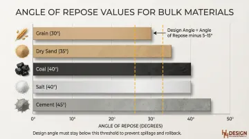
For loose, granular, or powdered materials—relevant to food, chemical, agricultural, and mining applications—incline design must account for angle of repose, the natural slope at which the material will slide. Typical values include:
- Grain: ~30°
- Sand (dry): ~35°
- Coal: ~40°
- Cement: ~45°
- Salt: ~40°
Materials with low angle of repose cannot be conveyed at steep angles without cleats or sidewalls to contain them. Design angle should be ≤ (angle of repose – 5° to 15°) to prevent spillage and rollback.
Bulk density and particle size also affect the maximum achievable angle. Heavier materials with large, irregular lumps often allow slightly steeper inclines — the lumps indent into the rubber cover, creating a mechanical holding action.
Light, fine materials like dry sand behave differently. They slide more easily and typically require lower incline angles than their bulk density alone would suggest.
Surface Finish and Friction Coefficient
The friction interaction between the product's bottom surface and the belt surface determines grip. Smooth-bottomed products on smooth belts at higher angles are inherently prone to slipping. This interaction must be verified through a physical tilt test rather than assumed from material specifications alone.
Moisture can reduce the coefficient of friction between the material and the belt, necessitating a lower incline angle.
Belt Type Selection for Inclined Applications
Belt selection is a direct consequence of incline angle and product type—no single belt type is universally optimal, and selecting the wrong belt is one of the most common and costly design errors in incline conveyor projects.
Flat Belts
Flat belts work best at lower incline angles (generally up to 18–20°) with unit loads that have sufficient contact friction against the belt surface. Surface texture—smooth, rough-top, or chevron—can extend the effective angle range modestly.
Chevron or rough-top patterns increase friction, allowing slightly steeper angles (up to ~25–30° depending on profile height). Material options include rubber, PVC, and food-grade variants.
Cleated Belts
Cleated belts are the right choice for steeper inclines (30–40°) where flat belts would allow product to slide backward. Cleats—raised flights perpendicular to belt travel—create positive product retention. Match cleat height, spacing, and profile to product dimensions carefully; products smaller than the cleat height can jam between cleats.
Cleated belts introduce additional considerations for the return path and cleaning access, particularly relevant in food and bulk chemical applications.
Running smooth belts at angles beyond their effective range accelerates wear and increases maintenance frequency. Using cleated belts at the appropriate angle range is the more reliable and lower-maintenance choice.
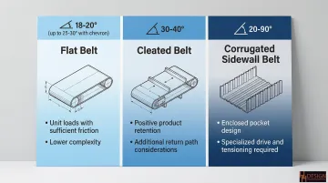
Corrugated Sidewall Belts
For bulk loose materials requiring steep or vertical lift, corrugated sidewall belts handle angles from 20° up to 90°. They combine lateral sidewalls with cross-cleats to form enclosed pockets, enabling angles up to 90°.
They are typically used for bulk loose materials and have specific drive and tensioning requirements distinct from flat or cleated belt designs. Corrugated sidewall belts require larger drive pulleys and shaft-mounted backstops to handle the increased tension and prevent rollback.
Matching belt type to the application is a core part of incline conveyor design. H&H Design Manufacturing builds incline conveyor systems with belt specifications selected to the exact incline angle, product type, and industry requirements of each project.
Drive and Motor Sizing Considerations
Motor and drive sizing for incline conveyors must be based on worst-case load conditions (fully loaded belt at maximum incline), not average throughput. Undersizing the drive is the most direct path to thermal overload, belt slippage at the drive pulley, and backstop mechanism failure when the conveyor stops under load.
Key Variables in Drive Sizing
The CEMA Universal Method is the standard for calculating effective belt tension (Te) and power requirements. The primary equation is:
Te = L·Kt(Kx + KyWb + 0.015Wb) + Wm(L·Ky + H) + Tp + Tam + Tac
Where:
- L = Conveyor Length
- H = Lift Height (vertical distance)
- Wm = Weight of Material (lbs/ft)
- Wb = Weight of Belt (lbs/ft)
- Kt, Kx, Ky = Friction and resistance factors
- Tp, Tam, Tac = Tensions from pulleys, material acceleration, and accessories
The term Wm × H represents the tension required solely to lift the material. On steep inclines, this gravity component often dominates the power requirement.
Variable Frequency Drives (VFDs)
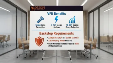
VFDs offer controlled acceleration and deceleration, which reduces shock loads on startup—particularly important for loaded incline conveyors in bulk material operations. Key advantages for incline applications include:
- Prevent the torque spike that causes belt lift-off or material rollback during starting
- Reduce energy consumption by 5–10% on conveyors with variable loading
- Cut startup shock loads by 40–60% compared to across-the-line starting
As a UL-certified industrial control panel shop, H&H Design Manufacturing engineers drive and control integration directly into the conveyor system specification—so electrical and mechanical design stay coordinated from the start.
Backstop and Holdback Requirements
When an incline conveyor stops under load, gravity will drive the belt backward unless a mechanical backstop or VFD with dynamic braking is specified. This is a safety-critical design requirement, not an optional feature.
Applicable standards and specification requirements include:
- ASME B20.1-2024 and 30 CFR 56.14113 both mandate anti-runaway devices on all inclined conveyors
- Omitting a backstop risks runaway belt, equipment damage, and personnel injury
- Shaft-mounted backstops must be fitted on the drive pulley, with capacity rated at ≥ 150% of maximum load
Spatial Constraints and Conveyor Geometry
Available facility space sets hard limits on conveyor geometry. The horizontal floor run, headroom at the discharge point, and infeed/discharge height together determine the achievable angle range — and this needs to be established before any belt or drive analysis begins.
Rise/Run Relationship
For any fixed elevation change, a longer conveyor run produces a shallower angle (favoring simpler belt and drive solutions), while a shorter run forces a steeper angle (requiring more specialized belt and drive configurations). Engineers should calculate this trade-off early and communicate it to facility planners before finalizing the layout.
Example: To achieve a 10-foot vertical rise:
- At 18° angle: requires 31-foot horizontal run
- At 30° angle: requires 17-foot horizontal run
- At 60° angle: requires 6-foot horizontal run
A steep-angle pocket belt can cut the required horizontal run by 50% or more. The trade-offs are:
- Higher belt tension
- Increased power consumption
- More complex belt construction
Alternative Designs
Sometimes the available footprint simply won't accommodate a standard belt conveyor at a safe angle. In those cases, alternative configurations are worth evaluating:
- Z-conveyors (swanneck): Max ~30°, adds horizontal top segment, moderate footprint
- Spiral conveyors: Up to 45°, compact footprint, lower capacity
- Bucket elevators: Vertical lift only, highest capacity, highest cost
Select equipment based on required lift angle, space constraints, and throughput — not by forcing an over-steep flat-belt design into a layout it doesn't fit.
Common Design Mistakes and Their Consequences
Designing to Absolute Limits
The most frequent error is treating published maximum angle specifications as safe operating targets rather than absolute limits. Designing to 25° when 25° is the tested ceiling leaves no margin for load variation, belt wear, or environmental factors. System failures typically appear after weeks or months of marginal operation rather than immediately.
Ignoring Product-Belt Interaction
Slippage causes product damage and throughput loss. Beyond product damage, repeated slippage events accelerate belt surface wear and drive pulley wear. In bulk material applications, a slipping belt spills material onto the floor — creating cleanup demands, contamination risks, and slip hazards for workers nearby.
Skipping Physical Testing
Specifying belt type and drive without conducting a physical tilt test on the actual product creates a design that works at commissioning but fails under real conditions. Changes in product state — temperature shifts, moisture uptake, packaging changes — can alter friction coefficients enough to trigger slippage that never appeared during initial testing.
Undersizing the Drive
The same under-accounting that causes slippage failures also shows up in drive sizing. Failing to include Tam (material acceleration force) and Wm × H (full gravity load) in startup calculations causes the conveyor to stall under load. Motor sizing must cover worst-case scenarios — not average operating conditions.
Omitting Backstops
Even a shallow incline can generate significant rollback energy with a fully loaded belt. Without a mechanical backstop or dynamic braking on the drive, a loaded incline conveyor will run backward under gravity, potentially damaging the belt, drive components, and the product.
Frequently Asked Questions
What is the maximum incline angle for a belt conveyor?
Standard flat-belt conveyors are generally limited to 18–25° depending on product type and belt surface. Cleated belts can accommodate steeper angles up to 40–45°, while corrugated sidewall belts can handle angles up to 90° (vertical). The actual safe limit is determined by a product tilt test rather than a universal rule.
What causes material rollback on an incline conveyor?
Rollback occurs when the gravitational force on the load exceeds the friction grip between the product/material and the belt surface. It is typically triggered by incline angle exceeding the belt-product friction limit, belt slippage at the drive pulley, or conveyor stoppage without a backstop device.
How do I choose between a cleated belt and a flat belt for an incline conveyor?
Flat belts suit lower-angle applications (up to 18–20°) with unit loads that have adequate contact friction. Cleated belts are required at steeper angles or with products prone to sliding. Base the decision on incline angle, product dimensions, and whether the product geometry is compatible with the cleat profile.
How is motor power calculated for an incline belt conveyor?
Motor sizing must account for lift load (product weight × vertical rise), belt weight, belt speed, and drivetrain efficiency under worst-case fully loaded conditions. Add capacity margin for startup torque and surge loading. The CEMA Universal Method provides the standard calculation framework.
What happens if an incline conveyor is stopped under full load?
Without a mechanical backstop or dynamic braking, a loaded incline conveyor will run backward under gravity, damaging the belt, drive components, and product. Backstop specification is a safety-critical requirement under ASME B20.1 and 30 CFR 56.14113 — not optional.
When should I consider a Z-conveyor or spiral conveyor instead of a standard incline belt conveyor?
Consider alternatives when floor length is too short for a safe incline angle, or when the required angle exceeds what the product can tolerate on a flat or cleated belt. Z-conveyors, spiral conveyors, and bucket elevators reduce horizontal footprint but add complexity and power requirements.